Commands
Command Overview
The following table shows all main commands. The sub commands are only shown in case of differences between the firmware versions.
| Command | ID | all 05.xx.xx versions | all 06.xx.xx versions | all 07.xx.xx versions | all 08.00.xx versions | all 08.01.xx versions | all 08.02.xx versions | all 09.00.xx versions |
|---|---|---|---|---|---|---|---|---|
| ROUTE OUTPUT | 0x01F5xxxx | x | x | x | x | x | x | x |
| Set | len 4 | x | x | x(3) | x | x | x | x |
| Request one crosspoint | len 2 | x | x | x(3) | x | x | x | x |
| Request all | len 0 | x | - | - | - | - | - | - |
| Crosspoint notification | len1 | - | x(1) | x(2) | x | x | x | x |
| 32 bit Request | len 5 | - | x(1) | x(2) | x | x | x | x |
| 32 bit Set | len 8 | - | x(1) | x(2) | x | x | x | x |
| ARBITRATION | 0x01F90000 | - | - | x(6) | x | x | x | x |
| Set | len 5 | - | - | x(6) | x | x | x | x |
| Request | len 3 | - | - | x(6) | x | x | x | x |
| SETFADERON | 0x11020000,3 | x | x | x | x | x | x | x |
| SETFADER | 0x11030000 | x | x | x | x | x | x | x |
| Request | len 2 | x(4) | x | x | x | x | x | x |
| Fader value notification | len 1 | - | - | x(7) | x | x | x | x |
| SETCHACCESS | 0x11040000 | x | x | x | x | x | x | x |
| request | len 0 | x | - | - | - | - | - | - |
| SETCHINPUTNUMBER | 0x110D0000 | x | x | x | x | x | x | x |
| Request all | len 0 | x | - | - | - | - | - | - |
| SETLOGIC | 0x110E0000 | x | x | x | x | x | x | x |
| Request | len 2 | x | x | x | x | x | x | x |
| SETMONITORLEVEL | 0x11100000 | x | x | x | x | x | x | x |
| Set | len 6 | x | x | x | x | x | x | x |
| Request | len 2 | - | - | x(9) | x | x | x | x |
| SETCHDISPLAY | 0x11140000 | x | x | x | x | x | x | x |
| Request | len 3 | x | - | x(5) | x | x | x | x |
| SETPFL | 0x11160000 | x | x | x | x | x | x | x |
| on/auto mute | len 4 | x | - | - | - | - | - | - |
| switch off all | len 0 | x | - | - | - | - | - | - |
| switch off all on Virt.Mixer | len 1 | - | x | x | x | x | x | x |
| Request | len 2 | - | - | x(9) | x | x | x | x |
| LOADSAVE | 0x111C0000 | x | x | x | x | x | x | x |
| Set IO Gain | 0x112D0000 | x(4) | x | x | x | x | x | x |
| Set | len 4 | x(4) | - | - | - | - | - | - |
| Request | len 2 | x(4) | - | - | - | - | - | - |
| 32 bit Set | len 6 | - | x(1) | x(2) | x | x | x | x |
| 32 bit Request | len 4 | - | x(1) | x(2) | x | x | x | x |
| FADERTOUCH | 0x11820000,2 | x | x | x | x | x | x | x |
| METERING | 0x111D0000,2 | - | - | - | - | x(8) | x(8) | x(8) |
| CF In/Out Parameters | 0x11810000 | - | - | - | - | - | - | x(10) |
(1)since version 06.07.15 or any higher 06.07.xx version
(2)since version 07.01.16 or any higher version
(3)command 0x01F50000 32bit should be used instead
(4)since version 05.02.04 or any higher version
(5)since version 07.02.10 or any higher version
(6)since version 07.02.32 or any higher version
(7)since version 07.02.09 or any higher version
(8)since version 08.01.18
(9)since version 07.04.11 or any higher version
(10)since version 09.00.05 or any higher version
Set Routing
This command can change the output routing of a device.
Please note that there are two implementations of this command: 16 bit and 32 bit version. The use of the 32 bit command is recommended when a 52/XS/XC/XD or 52/XS2/XC2/XD2 device shall be controlled.
Set Output Routing - 0x01F5xxxx- 16bit
All Firmware Versions
On 52/XS/XC/XD or 52/XS2/XC2/XD2 devices the use of 32bit routing command (see Set Output Routing - 0x01F5xxxx- 32bit) is recommended.
| ID | Length | D0 | D1 | D2 | D3 | D4 | D5 | D6 | D7 |
|---|---|---|---|---|---|---|---|---|---|
| 0x01F5xxxx | 0/4 | OutputHi | OutputLo | InputHi | InputLo |
| Byte | Description | Values | Note |
|---|---|---|---|
| ID | xxxx | Number of the controller module (can be 0 for transmitting, ignore on receiving) | |
| D0,D1 | Output | 0x0180…0x1EFF | Number of the physical output |
| D2,D3 | Input | 0x0100…0x1E7F | Number of the physical input |
| 0x4000…0x7FFF | Summation and special channels | ||
| 0xFFFF | Mute | ||
| Length | 0 | Request for all crosspoints. Device answers with datagram of Length 4 for each crosspoint. | |
 | |||
| 2 | Request for one crosspoint; Device answers with datagram of Length 4 for the requested crosspoint. | ||
| 4 | Set crosspoint |
Examples:
01F50000,2,03,83 will request the crosspoint of slot 3, output port 4
01F50000,4,05,80,01,02 will route slot 1, input port 3 to slot 5, output port 1
Physical I/O Numbers
HiByte Slotnumber 1…30 (1…0x1E)
LoByte Input/Output Number within given slot (0…7, Madi 0…63/127)
| Inputs | Analog Inputs | 0x00…0x03 |
| Digital Inputs | 0x00…0x07 | |
| Single Madi Inputs | 0x00…0x37/0x3F | |
| Double Madi Inputs | 0x00…0x37/0x3F (0…55/63); 0x40/0x7F (64…119/127) | |
| Outputs marked with Bit 7 (0x80) | Analog Outputs | 0x80…0x83 |
| Digital Outputs | 0x80…0x87 | |
| Single Madi Outputs | 0x80…0xBF | |
| Double Madi Outputs | 0x80…0xBF; 0xc0…0xFF |
Set Output Routing - 0x01F5xxxx- 32bit
Series52 Firmware Versions:
- 06.07.15 or any higher 06.07.xx version
- 07.01.16 or any higher 07.xx.xx version
| ID | Length | D0 - D3 | D4 - D7 |
|---|---|---|---|
| 0x01F5xxxx | 1/5/8 | 32bit Output ID | 32bit Input ID |
| Byte | Description | Values | Note |
|---|---|---|---|
| ID | xxxx | Number of the controller module (can be 0 for transmitting, ignore on receiving) | |
| D0-D3 | 32bit Output ID | see AudioID Description below | |
| D4-D7 | 32bit Input ID | see AudioID Description below | |
| Length | 0 | not supported | |
| 1 | D0: 0x00 → Deactivate crosspoint notification | ||
| D0: 0x01 → Activate crosspoint notification (only available on TCP connections!); As soon as a DHD internal routing is carried out (DHD software or routing buttons on DHD hardware) a datagram of length 8 is sent as crosspoint information. | |||
 | |||
| 5 | Request for one crosspoint with 32bit OutputID at D0-D3. D4-D7 is empty. Device answers with datagram of length 8. | ||
 | |||
 | |||
| 8 | Set crosspoint with OutputID and InputID. Mute: InputID = 0x00000000 | ||
| |||
|
Examples:
01F50000,1,1	                        activates the crosspoint notification
01F50000,5,40,03,18,06	                will request the crosspoint of AudioID 0x40031806
01F50000,8,40,08,08,03,40,01,00,02	    sets a crosspoint on output 0x40080803 with source 0x40010002
AudioID description: 32bits Unique ID that identifies an audio signal within a TB5/TB8 project: Dependent on the hardware used, there are two different versions of the 32 bit AudioID. Independent from the version, the AudioIDs from a device should be looked up or exported from the project's TB5/TB8 configuration.
Version 1 - all 52/RM4200D and 52/XR devices:
| Pos. | Name | Description |
|---|---|---|
| 31...24 | DeviceID | DeviceID |
| 23 | internal | Audio signal is internal (i.e. buses) |
| 22 | phase | Not used, set to 0 |
| 21...16 | slot no. | Number of the slot within DSP-Frame (1…63) |
| 15...13 | empty | Set to 0 |
| 12 | stereo | Indicates a signal as stereo; Only indication! This bit has no influence on routing. Routing is always mono (set to 0). Bit should be ignored on set/request. |
| 11 | output | 1 = output, 0 = input |
| 10 | gpio | 1 = gpio, 0 = audio |
| 9...8 | madi | Number of MADI port (0,1) |
| 7...0 | channel | Channel (0 = left, 1 = right, 2 = left,………) |
Version 2 - all 52/XS, XC, XD devices:
| Pos. | Name | Description |
|---|---|---|
| 31...24 | DeviceID | DeviceID |
| 23...22 | format | Indicates a signal as mono, stereo or 5.1; Only indication! These bits do not have influence on routing. Routing is always mono (set to 0). Bit should be ignored on set/request. |
| 21...16 | reserved | Set to 0 |
| 15 | I/O flag | 1 = output, 0 = input |
| 14…0 | address | address of audio signal |
Set Arbitration - 0x01F90000
Series52 Firmware Versions:
- 07.02.32 or any higher 07.xx.xx version
| ID | Length | D0 - D3 | D4 |
|---|---|---|---|
| 0x01F90000 | 4/5 | 32bit Output / Input Audio ID | Device ID of owning device |
The ownership information on outputs is not used by our firmware for internal access or routing control, and can be seen like a simple information storage. In general, routings are always possible even if an Device ID is set. Any resource control on routings must be handled by the connected applications.
The Device ID on all Audio IDs is set to 0x00 after firmware reset / system reboot or power cycle.
| Byte | Description | Values | Note |
|---|---|---|---|
| D0-D3 | 32bit Output / Input Audio ID | see below | |
| D4 | Device ID | 0x00 | if Input / Output is unused/free, no owner |
| 0x40…0x60 | Device ID of owning device (see project's TB5/TB8 configuration on DHD or third party devices) | ||
| Length | 4 | Request arbitration of given Output / Input Audio ID. Device answers with datagram of length 5. | |
| 5 | • Answer on request or status change information. | ||
| • Set arbitration of given Output / Input Audio ID with Device ID. No confirmation will be send by the device. |
On 52/RM4200D and 52/XR devices the AudioID's stereo bit 12 should be ignored (see AudioID description).
On 52/XS/XC/XD or 52/XS2/XC2/XD2 devices AudioID format bits 22,23 should be ignored (see AudioID description).
Examples:
01F90000,4,40,03,18,06	        request owner of Audio ID 0x40031806
01F90000,5,40,03,18,06,65	    example answer: Device ID 0x65 owns Audio ID 0x40031806 (arbitration set)
01F90000,5,40,08,08,03,00	    example set command: Owner of AudioID 0x40080803 will be set to 0x00
                                (no owner)
01F90000,4,40,03,18,06,59	    example set command: Owner of AudioID 0x40031806 will be set to 0x59
                                (owning device has Device ID 0x59)
AudioID Description: 32bits
Unique ID that identifies an audio signal within a TB5/TB8 project:
Dependent on the hardware used, there are two different versions of the 32 bit AudioID. Independent from the version, the AudioIDs from a device should be looked up or exported from the project's TB5/TB8 configuration.
Version 1 - all 52/RM4200D and 52/XR devices:
| Pos. | Name | Description |
|---|---|---|
| 31...24 | DeviceID | DeviceID |
| 23 | internal | Audio signal is internal (i.e. buses) |
| 22 | phase | Not used, set to 0 |
| 21...16 | slot no. | Number of the slot within DSP-Frame (1…63) |
| 15...13 | empty | Set to 0 |
| 12 | stereo | Indicates a signal as stereo; Only indication! This bit has no influence on routing. Routing is always mono (set to 0). Bit should be ignored on set/request. |
| 11 | output | 1 = output, 0 = input |
| 10 | gpio | 1 = gpio, 0 = audio |
| 9...8 | madi | Number of MADI port (0,1) |
| 7...0 | channel | Channel (0 = left, 1 = right, 2 = left,………) |
Version 2 - all 52/XS, XC, XD devices:
| Pos. | Name | Description |
|---|---|---|
| 31...24 | DeviceID | DeviceID |
| 23...22 | format | Indicates a signal as mono, stereo or 5.1; Only indication! These bits do not have influence on routing. Routing is always mono (set to 0). Bit should be ignored on set/request. |
| 21...16 | reserved | Set to 0 |
| 15 | I/O flag | 1 = output, 0 = input |
| 14...0 | address | address of audio signal |
Set Monitor Channel - 0x11000000
All Firmware Versions
On 52/XS/XC/XD or 52/XS2/XC2/XD2 devices the use of 32bit routing command 0x01F5 is recommended.
This command switches the given monitor number to the set channel.
| ID | Length | D0 | D1 | D2 | D3 | D4 | D5 | D6 | D7 |
|---|---|---|---|---|---|---|---|---|---|
| 0x11000000 | 3/6 | InputHi Left | InputLo Left | Number | 0 | InputHi Right | InputLoRight |
| Byte | Description | Values | Note |
|---|---|---|---|
| D0,D1 | Input 16 bit Audio Address | 0x0000…0x0027 | PreFader Signal of the mixer |
| and | 0x0100...0x1E7F | Input of the mixer | |
| D4,D5 | 0x4000...0x7FFF | Summations and special channels | |
| D2 | Number of monitor (selector) channel | 0..5 | with firmware version 05.xx.xx |
| 0...199 | with firmware version 06.xx.xx and higher | ||
| Length | 3 | Request the current inputs of the given monitor (selector) channel at D2. D0,D1 should be 0x00 when requesting. Device answers with datagram of Length 6. | |
 | |||
| 6 | sets the given monitor (selector) channel to the given input values |
Examples:
11000000,6,03,00,05,00,03,01 routes input signal 1/2 from slot 3 onto monitor channel no. 6
06 00 11 00 00 00 03 00 05 00 03 01 (like transmitted) routes input signal 1/2 from slot 3 onto monitor channel no. 6
Switch Fader/Channel On/Off - 0x11020000
All Firmware Versions
Mixer fader/channel is switched on or off
| ID | Length | D0 | D1 | D2 | D3 | D4 | D5 | D6 | D7 |
|---|---|---|---|---|---|---|---|---|---|
| 0x11020000 | 3 | FaderHi | FaderLo | On |
| Fader | Versions 05.xx.xx: | |
|---|---|---|
| FaderLo: 0x00…0x27 | Fader of the mixer | |
| FaderHi: 0x00 | not used | |
| Versions 06.xx.xx and higher: | ||
| FaderLo: 0x00...0x2F | LogicFader no. 1…48 per virtual mixer | |
| FaderHi: 0x00 | Virtual Mixer 1; FaderLo denotes LogicFader | |
| FaderHi: 0x01 | Virtual Mixer 2; FaderLo denotes LogicFader | |
| FaderHi: 0x02 | Virtual Mixer 3; FaderLo denotes LogicFader | |
| FaderHi: 0x03 | Virtual Mixer 4; FaderLo denotes LogicFader | |
| FaderHi: 0x10 | FaderLo denotes Fader Channel Number (1...150) in one of the Virtual Mixers | |
| On | 1 Switch on/0 Switch off |
Examples:
0x11020000,3,00,05,01	will switch fader no. 6 at Virtual Mixer 1 to ON - this is independent of the assigned Fader Channel.
0x11020000,3,02,16,00	will switch fader no. 23 at Virtual Mixer 3 to OFF - this is independent of the assigned Fader Channel.
0x11020000,3,10,4D,00	will switch channel no. 77 to OFF - this is independent of fader and layer assignment
Set Fader Level - 0x11030000
All Firmware Versions
Set fader/channel to given level.
| ID | Length | D0 | D1 | D2 | D3 | D4 | D5 | D6 | D7 |
|---|---|---|---|---|---|---|---|---|---|
| 0x11030000 | 1/2/4/7 | FaderHi | FaderLo | LevelHi | LevelLo | TimeHi | TimeLo | Type |
| Byte | Description | Values | Note |
|---|---|---|---|
| D0 | FaderHi | Firmware Versions 05.xx.xx: | |
| 0x00 | not used | ||
| Firmware Versions 06.xx.xx and higher: | |||
| 0x00 | Virtual Mixer 1; FaderLo denotes LogicFader | ||
| 0x01 | Virtual Mixer 2; FaderLo denotes LogicFader | ||
| 0x02 | Virtual Mixer 3; FaderLo denotes LogicFader | ||
| 0x03 | Virtual Mixer 4; FaderLo denotes LogicFader | ||
| 0x10 | FaderLo denotes Fader Channel Number (1…150) in one of the Virtual Mixers | ||
| D1 | FaderLo | Firmware Versions 05.xx.xx: | |
| 0x00...0x27 | Fader of the mixer | ||
| Firmware Versions 06.xx.xx and higher: | |||
| 0x00…0x2F | LogicFader no. 1…48 per virtual mixer | ||
| D2,D3 | Level | 0x8000…0x7FFF | -327.68 dB…327.67 dB |
| D4,D5 | Time | 0x0000…0x2000 | Time in ms |
| D6 | Type | 0 | Level linear fade |
| 1 | Fader linear fade | ||
| Length | 1 | fader value notification (Firmware 07.02.09 or higher) | |
 | |||
| D0: 0x00 → Deactivate notification | |||
| D0: 0x01 → Activate fader value notification; As soon as a fader value is changed a datagram of length 4 is sent as fader value information (FaderHi is 0x00…0x03) | |||
| 2 | request for fader level (Firmware 05.02.03 or higher) | ||
| 4 | set fader level | ||
| 7 | set fader level within time |
Set Fader Access 0x11040000
All Firmware Versions Set Access function to fader.
| ID | Length | D0 | D1 | D2 | D3 | D4 | D5 | D6 | D7 |
|---|---|---|---|---|---|---|---|---|---|
| 0x11040000 | 0/7 | FaderHi | FaderLo | On | Type | ChannelHi | ChannelLo | ACC Group |
| Byte | Description | Values | Note |
|---|---|---|---|
| D0 | FaderHi | Firmware Versions 05.xx.xx: | |
| 0x00 | not used | ||
| Firmware Versions 06.xx.xx and higher: | |||
| 0x00 | Virtual Mixer 1; FaderLo denotes LogicFader | ||
| 0x01 | Virtual Mixer 2; FaderLo denotes LogicFader | ||
| 0x02 | Virtual Mixer 3; FaderLo denotes LogicFader | ||
| 0x03 | Virtual Mixer 4; FaderLo denotes LogicFader | ||
| 0x10 | FaderLo denotes Fader Channel Number (1…150) in one of the Virtual Mixers | ||
| D1 | FaderLo | Firmware Versions 05.xx.xx: | |
| 0x00...0x27 | Fader of the mixer | ||
| Firmware Versions 06.xx.xx and higher: | |||
| 0x00…0x2F | LogicFader no. 1…48 per virtual mixer | ||
| D2 | On | 0 | Access is switched off |
| 1 | Access is switched on | ||
| D3 | Type | 0 | Access function is GAIN |
| 1 | Access function is PAN/BAL | ||
| 2 | Access function is INPUTSELECT | ||
| D4-D5 | Channel | 1...150 | Channel Number (only used in answer of request status command) |
| D6 | Acc-Group | 0...5 | Acc-Group 1…6 (only used in answer of request status command) |
| Length | 0 | Request Access status | |
| |||
| 7 | Set Access |
Set Channel Input Number - 0x110D0000
| ID | Length | D0 | D1 | D2 | D3 | D4 | D5 | D6 | D7 |
|---|---|---|---|---|---|---|---|---|---|
| 0x110D0000 | 0/2/4 | FaderHi | FaderLo | ChannelHi | ChannelLo |
| Byte | Description | Values | Note |
|---|---|---|---|
| D0 | FaderHi | Firmware Versions 05.xx.xx: | |
| 0x00 | not used | ||
| Firmware Versions 06.xx.xx and higher: | |||
| 0x00 | Virtual Mixer 1; FaderLo denotes LogicFader | ||
| 0x01 | Virtual Mixer 2; FaderLo denotes LogicFader | ||
| 0x02 | Virtual Mixer 3; FaderLo denotes LogicFader | ||
| 0x03 | Virtual Mixer 4; FaderLo denotes LogicFader | ||
| D1 | FaderLo | Firmware Versions 05.xx.xx: | |
| 0x00...0x27 | Fader of the mixer | ||
| Firmware Versions 06.xx.xx and higher: | |||
| 0x00…0x2F | LogicFader no. 1…48 per virtual mixer | ||
| D2-D3 | Channel | 0x0001…0x00BA | defined Fader Channel Number (1…250) in TB5/TB8 configuration |
| Length | 0 | Request all | |
 | |||
| 2 | Request input for Fader | ||
| 4 | Set Channel Input to Fader (Input Select) |
Set Internal Logic States - 0x110E0000
| ID | Length | D0 | D1 | D2 | D3 | D4 | D5 | D6 | D7 |
|---|---|---|---|---|---|---|---|---|---|
| 0x110E0000 | 2/3 | LogicIDHi | LogicIDLo | On |
| Byte | Description | Values | Note |
|---|---|---|---|
| D0-D1 | LogicID |  | |
 | |||
| D2 | On | 0 | Logic false /off |
| 1 | Logic true /on | ||
| Length | 2 | Request logic state. Device answers with datagram of length 3. | |
| 3 | Set logic state. |
The fixed Logic addresses from the following table are only valid for firmware versions 05.xx.xx (not valid for current Series 52 systems, see note above)!
| Address range | Description |
|---|---|
| 0 | OFF |
| 1…384 | 12*32 Pushbuttons Start (DeviceID-1)*32+1, size 32 or 64 depending on module size |
| 385…480 | GPIs 3 backplanes * 8 slots * 4 GPIs = 96 |
| 481…630 | Fader start related to defined channel |
| 631…780 | Fader function related to defined channel |
| 781…930 | PFL is switched on related to defined channel |
| 931…1080 | 150 Logic functions |
| 1081…1280 | Global Logics |
| 1281 | PFL On |
| 1282…1284 | PULSE1…PULSE2 (internal use only) |
| 1285 | OFF-AIR |
| 1286 | Voice/Music signalisation |
| 1287 | PGM1 Logic |
| 1288 | Timer Running |
| 1289 | Timer Reset |
| 1290…1295 | MADI failure indication 3 slots with 2 ports |
| 1296 | SOLO |
| 1297…1380 | reserved |
| 1381…1400 | Logic Delay |
| 1401…1415 | Level Detect |
| 1416…1445 | Preparation conference related to clean feeds |
| 1446…1475 | Talk logic related to clean feeds |
| 1476…1505 | Off-Air logic related to clean feeds |
| 1506…1535 | Output select logic related to clean feeds |
| 1536…1685 | Rotary select |
| 1686…1725 | Fader start related to fader |
| 1726…1999 | reserved |
Set Monitor Level - 0x11100000
All Firmware Versions
The potentiometer is set to given level.
| ID | Length | D0 | D1 | D2 | D3 | D4 | D5 | D6 | D7 |
|---|---|---|---|---|---|---|---|---|---|
| 0x11100000 | 2/4/7 | PotHi | PotLo | LevelHi | LevelLo | TimeHi | TimeLo | Type |
| Byte | Description | Values | Note |
|---|---|---|---|
| D0-D1 | Pot | 0x0000...0x0077 | Potentiometer 1…120 |
| |||
| D2-D3 | Level | 0x8000...0x7FFF | -327.68dB…327.67dB |
| D4-D5 | Time | 0x0000...0x2000 | Time in ms |
| D6 | Type | 0 | level linear fade |
| 1 | fader linear fade | ||
| Length | 2 | Request value of Pot. Device answers with Datagram of Length 4. | |
| |||
| 4 | Level is set instantly. Timing information and type is ignored. | ||
| 7 | Level is set within given time using the given type. |
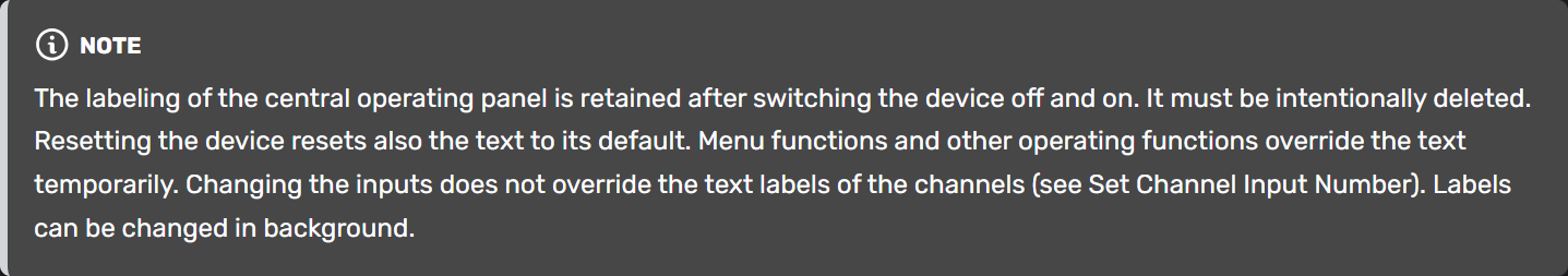
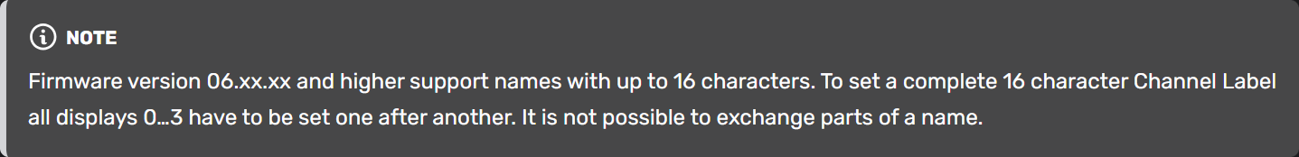
Set Display or Channel Label - 0x11140000
All Firmware Versions
The display labelling can be changed.
| ID | Length | D0 | D1 | D2 | D3 | D4 | D5 | D6 | D7 |
|---|---|---|---|---|---|---|---|---|---|
| 0x11140000 | 2/3/8 | ChannelHi | ChannelLo | Display Nr. | ASCII1 | ASCII2 | ASCII3 | ASCII4 |
| Byte | Description | Values | Note |
|---|---|---|---|
| D0-D1 | Channel | 0x0001…0x00BA | Channel Number (1..250) of the mixer. See TB5/TB8 config for Channel Numbers in use. |
| 0x8001…0x800C | Central operating panel (Module ID 1…Module ID 12) | ||
 | |||
 | |||
| D2 | Display Nr | 0x00...0x7F | Each Display has 4 characters |
| D4,D5,D6,D7 | ASCII | 0x00…0x7F | Characters |
| Length | 2 | reproduces the original text (in central operating panel: deleting one segment deletes all segments) | |
| 3 | request for the channel label | ||
 | |||
| 8 | sets channel label / central operating panel | ||
 |
Set PFL - 0x11160000
All Firmware Versions
This command switches the PFL of each channel.
| ID | Length | D0 | D1 | D2 | D3 | D4 | D5 | D6 | D7 |
|---|---|---|---|---|---|---|---|---|---|
| 0x11160000 | 0/1/2/4 | FaderHi | FaderLo | On | Auto Mute |
| Byte | Description | Values | Note |
|---|---|---|---|
| D0 | FaderHi | Firmware Versions 05.xx.xx: | |
| 0x00 | not used | ||
| Firmware Versions 06.xx.xx and higher: | |||
| 0x00 | Virtual Mixer 1; FaderLo denotes LogicFader | ||
| 0x01 | Virtual Mixer 2; FaderLo denotes LogicFader | ||
| 0x02 | Virtual Mixer 3; FaderLo denotes LogicFader | ||
| 0x03 | Virtual Mixer 4; FaderLo denotes LogicFader | ||
| 0x10 | FaderLo denotes Fader Channel Number (1…150) in one of the Virtual Mixers | ||
| D1 | FaderLo | Firmware Versions 05.xx.xx: | |
| 0x00…0x27 | Fader of the mixer | ||
| Firmware Versions 06.xx.xx and higher: | |||
| 0x00…0x2F | LogicFader no. 1…48 per virtual mixer | ||
| D2 | On | 1 | PFL on |
| 0 | PFL off | ||
| D3 | Auto Mute | 1 | All other channels are switched PFL off |
| 0 | the other channels remain unchanged | ||
| |||
| Length | 0 | Switch off all | |
 | |||
| 1 | Versions 05.xx.xx: not supported | ||
| Versions 06.xx.xx and higher: Switch off all PFL on given Virtual Mixer 1…4 (D0) | |||
| 2 | Request the PFL state of the given Virtual Mixer / Fader Channel Number (D0,D1). Device answers with datagram of Length 4. | ||
|
Load Save Setups - 0x111C0000
Firmware Version:
- 05.xx.xx Versions
| ID | Length | D0 | D1 | D2 | D3 | D4 | D5 | D6 | D7 |
|---|---|---|---|---|---|---|---|---|---|
| 0x111C0000 | 3/4 | Action | Snapshot Number | MixerID | Fader/Channel |
| Byte | Description | Values | Note |
|---|---|---|---|
| D0 | Action | 0x00 | Load Channel Snapshot → Length 4 |
| 0x01 | Save Channel Snapshot → Length 4 | ||
| 0x0a | Load Mixer Snapshot → Length 3 | ||
| 0x0b | Save Mixer Snapshot → Length 3 | ||
| D1 | Snapshot Number | 0x0…0x14 | Mixer Snapshot (0…20) |
| 0x0…0xFA | Channel Snapshot: 0…250 | ||
| D2 | MixerID | 0x00 | Virtual Mixer 1; D3 denotes Fader |
| 0x01 | Virtual Mixer 2; D3 denotes Fader | ||
| 0x02 | Virtual Mixer 3; D3 denotes Fader | ||
| 0x03 | Virtual Mixer 4; D3 denotes Fader | ||
| 0x10 | D3 denotes Channel in one of the Virtual Mixers | ||
| D3 | Fader/Channel | 0x00…0x2F | Number of Fader (0…47) |
| 0x00…0x96 | Number of Channel (0…250) |
Set IO Gain
This command can change the Input or Output Gain.
There are two implementations of this command: 16 bit and 32 bit version. The use of the 32 bit command is recommended when a 52/XS/XC/XD or 52/XS2/XC2/XD2 device shall be controlled.
Changes on I/O gain are valid until you restart the system (Reset or Power ON). You can not change this parameter from the console!
Set IO Gain - 0x112D0000 - 16bit
Firmware Version:
- 5.02.04 or any higher 05.xx.xx version
| ID | Length | D0 | D1 | D2 | D3 | D4 | D5 | D6 | D7 |
|---|---|---|---|---|---|---|---|---|---|
| 0x112D0000 | 2/4 | I/O Hi | I/O Lo | Value Hi | Value Lo |
| Byte | Description | Values | Note |
|---|---|---|---|
| D0-D1 | Output | 0x0180…0x1EFF | Number of the physical output |
Input | 0x0100…0x1E7F | Number of the physical input | |
| 0x4000…0x7FFF | Summation and special channels | ||
| 0xFFFF | Mute | ||
| D2-D3 | Value | 0x8000…0x7FFF | Gain -327.68dB … 327.67dB |
| Length | 2 | Request actual Gain | |
| 4 | Set Gain for I/O |
Physical I/O Numbers
| HiByte | Slotnumber 1...30 (1...0x1E) |
| LoByte | Input/Output Number within given slot (0…7, Madi 0…63/127) |
| Inputs | Analog Inputs | 0x00…0x03 |
| Digital Inputs | 0x00…0x07 | |
| Single Madi Inputs | 0x00…0x37/0x3F | |
| Double Madi Inputs | 0x00…0x37/0x3F (0…55/63), 0x40/0x7F (64…119/127) | |
| Outputs marked with Bit 7 (0x80) | Analog Outputs | 0x80…0x83 |
| Digital Outputs | 0x80…0x87 | |
| Single Madi Outputs | 0x80…0xBF | |
| Double Madi Outputs | 0x80…0xBF, 0xc0…0xFF |
Set IO Gain - 0x112D0000 - 32bit
Firmware Version:
- 06.07.15 or any higher 06.07.xx version
- 07.01.16 or any higher version
| ID | Length | D0 | D1 | D2 | D3 | D4 | D5 | D6 | D7 |
|---|---|---|---|---|---|---|---|---|---|
| 0x112D0000 | 4/6 | I/O Hi | I/O Lo | Value Hi | Value Lo |
| Byte | Description | Values | Note |
|---|---|---|---|
| D0-D3 | AudioID | see table below | |
| D4-D5 | Value | 0x8000 … 0x7FFF | Gain - 327.68dB … 327.67dB |
 | |||
| Length | 4 | Request actual Gain with 32bit AudioID (see AudioID description); Device answers with datagram of length 6. | |
| 6 | Set Gain for given Input /Output |
AudioID description: 32bits
Unique ID that identifies an audio signal within a TB5/TB8 project:
Dependent on the hardware used, there are two different versions of the 32 bit AudioID. Independent from the version, the AudioIDs from a device should be looked up or exported from the project's TB5/TB8 configuration.
Version 1 - all 52/RM4200D and 52/XR devices:
| Pos. | Name | Description |
|---|---|---|
| 31...24 | DeviceID | DeviceID |
| 23 | internal | Audio signal is internal (i.e. buses) |
| 22 | phase | Not used, set to 0 |
| 21...16 | slot no. | Number of the slot within DSP-Frame (1…63) |
| 15...13 | empty | Set to 0 |
| 9...8 | madi | |
| 12 | stereo | Indicates a signal as stereo; Only indication! This bit has no influence on routing. Routing is always mono (set to 0). Bit should be ignored on set request. |
| 11 | output | 1 = output, 0 = input |
| 10 | gpio | 1 = gpio, 0 = audio |
| 9...8 | channel | Number of MADI port (0,1) |
| 7...0 | channel | Channel (0 = left, 1 = right, 2 = left,………) |
Version 1 - all 52/XS, XC, XD devices:
| Pos. | Name | Description |
|---|---|---|
| 31...24 | DeviceID | DeviceID |
| 23...22 | format | Indicates a signal as mono, stereo or 5.1; Only indication! These bits do not have influence on routing. Routing is always mono (set to 0). Bit should be ignored on set/request. |
| 21...16 | reserved | Set to 0 |
| 15 | I/O flag | 1 = output, 0 = input |
| 14…0 | address | address of audio signal |
Motorfader Touched - 0x11820000
All Firmware Versions
This command is automatically transmitted by a DHD device when motorized faders are installed and touched by a user.
| ID | Length | D0 | D1 | D2 | D3 | D4 | D5 | D6 | D7 |
|---|---|---|---|---|---|---|---|---|---|
| 0x11820000 | 2 | ChannelNr. | Touch |
| Byte | Description | Values | Note |
|---|---|---|---|
| D0 | ChannelNr | 0x01…0xFA | Fader Channel Number (1…250) from TB5/TB8 configuration |
| D1 | Touch | 1 | Fader touched |
| 0 | Fader not touched |
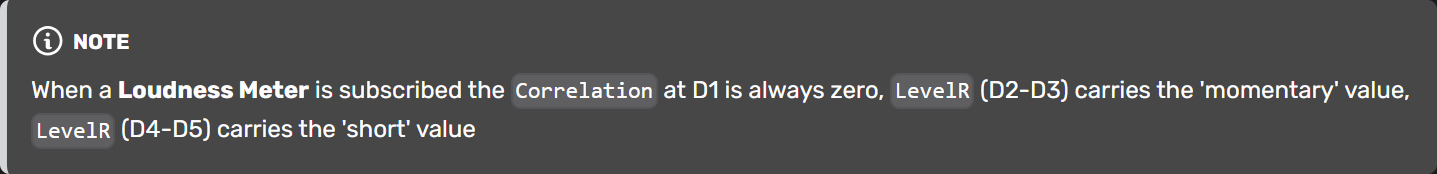
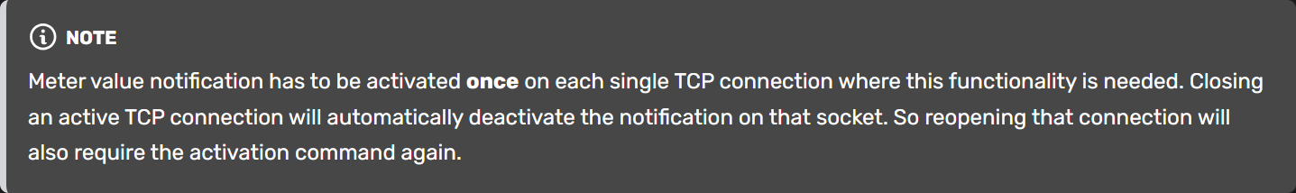
Metering - 0x111D0000
Firmware V8.01.18 or higher
| ID | Length | D0 | D1 | D2 | D3 | D4 | D5 | D6 | D7 |
|---|---|---|---|---|---|---|---|---|---|
| 0x111D0000 | 2 | Leveldetect | ON | ||||||
| 6 | Leveldetect | Correlation | LevelL Hi | LevelL Lo | LevelR Hi | LevelR Lo |
| Byte | Description | Values | Note |
|---|---|---|---|
| D0 | Leveldetect | 0x1…30 | Position of Leveldetect, True Peak Meter or Loudness Meter (1…48) as defined in TB8 configuration |
 | |||
| D1 | ON | 0 | deactivate meter notification |
| 1 | activate meter notification; As soon as a level is changed a datagram of length 6 is sent from the device. | ||
 | |||
| D1 | Correlation | -100..0..100 | equals the correlation from -1.00..0.00..1.00 |
| D2-D3 | LevelL | 0x8000…0x7FFF | -327.68 dB…327.67 dB (data value format is “signed short”) |
| D4-D5 | LevelR | 0x8000…0x7FFF | -327.68 dB…327.67 dB (data value format is “signed short”) |
Get / Set Parameter - 0x11810000 - CleanFeed Input
Firmware V9.0.5 or higher
| ID | Length | D0 | D1 | D2 | D3 | D4-D7 |
|---|---|---|---|---|---|---|
| 0x11810000 | 4 | ChannelHi | ChannelLo | 00 | 24 | |
| 8 | ChannelHi | ChannelLo | 00 | 24 | 32bit CFIn Parameter |
| Byte | Description | Values | Note |
|---|---|---|---|
| D0-D1 | Channel | 0x0001…0x00BA | Channel Number (1..250) of the mixer. See TB9 config for Channel Numbers in use. |
| D2-D3 | CFIn Prefix | 0x0024 | mandatory to operate this parameter |
| D4-D7 | 32bit - CFIn Parameter | - | Parameter set; see table below for the single parameters |
 | |||
| Length | 4 | Request current value | |
| 8 | - Set Parameter | ||
| - Answer on request | |||
| - Value information - sent when value changes internally |
32bit - CFIn Parameter:
| Pos. | Function | Value | Description |
|---|---|---|---|
| 31…8 | unused | 0 | bits not used - should be set to zero, ignore on receive |
| 7…0 | CF Input Gain/Attenuation | 0xD8…0x00…0x0F | -40…0…+15 dB |
Get / Set Parameter - 0x11810000 - CleanFeed Out
Firmware V9.0.5 or higher
This command only works with Channels that are defined as a Clean Feed (n-1) in the Toolbox configuration.
| ID | Length | D0 | D1 | D2 | D3 | D4-D7 |
|---|---|---|---|---|---|---|
| 0x11810000 | 4 | ChannelHi | ChannelLo | 00 | 25 | |
| 8 | ChannelHi | ChannelLo | 00 | 25 | 32bit CFOut Parameter |
| Byte | Description | Values | Note |
|---|---|---|---|
| D0-D1 | Channel | 0x0001…0x00BA | Channel Number (1..250) of the mixer. See TB9 config for Channel Numbers in use. |
| D2-D3 | CFIn Prefix | 0x0025 | mandatory to operate this parameter |
| D4-D7 | 32bit - CFIn Parameter | - | Set of several parameters; see table below for the single parameters |
| |||
| Length | 4 | Request current value | |
| 8 | - Set Parameter | ||
| - Answer on request | |||
| - Value information - sent when value changes internally |
32bit - CFOut Parameter:
| Pos. | Function | Value | Description |
|---|---|---|---|
| 31...19 | unused | 0 | bits not used - should be set to zero, ignore on receive |
| 18 | N-Mix On/Off bit | 0 | CF is n-1 signal |
| 1 | N-Mix on == the complete audio bus (without the '-1') is sent | ||
| 17 | Alternative Source On/Off bit | 0 | standard CF signal is sent |
| 1 | Alternative Source (from selected list position) is sent | ||
| 16 | CF Mute On/Off bit | 0 | unmuted |
| 1 | muted | ||
| 15...8 | Alternative Out Source List Position | 0x00…0x7F | Current alternative source; This source is used if the Alternative Source On/Off bit is 1 |
 | |||
| 7...0 | CF Out Gain/Attenuation | 0xD2…0x00…0x0a | -30…0…+10 dB |