Communication
The DHD External Control Protocol can be used on TCP/IP or serial interface to control the DHD devices from external systems.
The following table shows the availability of these interfaces dependent on the various frame/controller types:
| Frame type | Controller type | RS232 | RS422 | TCP |
|---|---|---|---|---|
| RM4200D DSP Frame | RM420-850 | 1 port on RM420-850 controller + 1 to 3 ports on each RM420-851 DSP Controller (max. 4 ports) | - | max. 10 sockets(1) |
| RM4200D DSP Frame | RM420-852 | 1 to 3 port on each RM420-851 DSP Controller (max. 3 ports) | 1 port | max. 10 sockets(2) |
| RM420-853 | 1 to 3 port on each RM420-851 DSP Controller (max. 3 ports) | Only on RM420-852B / RM420-853B! | max. 10 sockets(2) | |
| XR Router | 52-6850 | 1 port | 1 port | max. 10 sockets(2) |
| 52-6851 | 52-5862 RS232/RS232 card required | 52-5860 RS232/RS422 card required! | max. 10 sockets(2) | |
| XS Core | 52-1801 | 1 port on XS Core | - | max. 10 sockets(2) |
| 52-1804 | 1 port on XS Core | - | max. 10 sockets(2) | |
| XC Core | 52-7400 | 1 port on XC Core | - | max. 10 sockets(2) |
| 52-7402 | 1 port on XC Core | - | max. 10 sockets(2) | |
| 52-7403 | 1 port on XC Core | - | max. 10 sockets(2) | |
| XD Core | 52-7440/7450 | max. 2 ports on 52-7450 Controller | max. 2 ports on 52-7450 Controller | max. 10 sockets(2) |
| 52-7441/7450 | max. 2 ports on 52-7450 Controller | max. 2 ports on 52-7450 Controller | max. 10 sockets(2) | |
| 52-7442/7450 | max. 2 ports on 52-7450 Controller | max. 2 ports on 52-7450 Controller | max. 10 sockets(2) | |
| XS2 Core | 52-1810 | 1 port on XS2 Core | - | max. 10 sockets |
| 52-1830 | 1 port on XS2 Core | - | max. 10 sockets | |
| XC2 Core | 52-7423 | 1 port on XC2 Core | - | max. 10 sockets |
| 52-7420 | 1 port on XC2 Core | - | max. 10 sockets | |
| 52-7410 | 1 port on XC2 Core | - | max. 10 sockets | |
| XD2 Core | 52-7440/7456 | max. 2 ports on 52-7456 Controller | max. 2 ports on 52-7456 Controller | max. 10 sockets |
| 52-7441/7456 | max. 2 ports on 52-7456 Controller | max. 2 ports on 52-7456 Controller | max. 10 sockets | |
| 52-7442/7456 | max. 2 ports on 52-7456 Controller | max. 2 ports on 52-7456 Controller | max. 10 sockets |
((1) : max. 4 sockets possible when using Firmware Version 05.05.27…05.06.01)
((2) : max. 5 sockets until Firmware Version 7.04.06)
Please check module documentation for electrical specifications and pin assignment on RS232 and RS422 interfaces.
Serial Communication
Data Transmission
The parameters of the serial port are: 38400, 8, N, 1 no protocol
The values 0x00…0x1F are reserved as control bytes. If data belongs into this range, they are replaced by the following two bytes DLE, value+0x20.
Blocks are sent only in one direction, they are only answered with either ACK or NAK. As an answer with data, another block is sent.
Structure of a block:
| STX | 0,0,0,0,L3…L0 | 0,0,0,ID28…ID24 | ID23…ID16 | ID15…ID8 | ID7…ID0 | D0…Dn | PS | EOT

|STX       |0x02
|L3…L0     |Information on length - value between 0…8 (byte(s))
|ID28…ID0  |Command ID according to command description
|D0…Dn     |Data (0-8 Byte)
|PS        |Checksum according to the formula below
|EOT       |0x08
|DLE       |0x0A
|ACK       |0x06
|NAK       |0x05
This block is answered either with ACK or NAK. The block must be answered within 80 ms. After this time, the block is repeated. Each block is repeated three times maximum, after that the transmission of the block is canceled. The serial port has a buffer that can store up to 100 blocks. If this buffer is full because all blocks have to be repeated (no throughput), additional blocks are rejected.
The checksum is calculated over the original Data. For every Byte from Length to last Data Byte do the following:
Checksum = Checksum + (Byte xor 0xAA)

Checksum = Checksum * 2
Example
static unsigned int TxPS;
void SendByte(unsigned char Byte, int Control) {
int i;
 if (!Control) { /* calculate Checksum */
 	TxPS += (Byte^0xAA);
 	TxPS <<= 1;
 }
 if ((!Control) && (Byte<0x20)) {
 	SendChar(COM, DLE);
 	Byte += (unsigned char)0x20;
 }
 SendChar(COM, Byte);
}
Transmission Routine
for (; RepCnt>0; RepCnt--) {
 	TxPS = 0;
 // Send block
 SendByte(STX, 1);
 B = (unsigned char)(Block.Length);
 SendByte(B, 0);
 B = (unsigned char)((Block.ID & 0x1F000000L)>>24);
 SendByte(B, 0);
 B = (unsigned char)((Block.ID & 0x00FF0000L)>>16);
 SendByte(B, 0);
 B = (unsigned char)((Block.ID & 0x0000FF00L)>>8);
 SendByte(B, 0);
 B = (unsigned char)((Block.ID & 0x0000000FFL));
 SendByte(B, 0);
 for (i=0; i<Block.Length; i++) SendByte(Block.Data[i], 0);
 SendByte((unsigned char)TxPS, 0); /* transmit Checksum */
 SendByte(EOT, 1);
 if (!ByteComReceiveTimed(&B, 80)) {
    ErrCnt++;
 }
 else {
    if (B==ACK) {
       ErrCnt=0;
       break;
    }
 }
}
Functional Principle
All blocks received over a serial port are either routed to the central communication controller or to the internal CAN-bus, dependent on the Frame Type/ Controller Type (see Introduction for further background).
All blocks of a defined type are routed to the serial port by either the central communication controller or the CAN-bus, dependent on the Frame Type/ Controller Type.
Description of Data Blocks
Only the necessary data blocks are described. The device transmits additional blocks that have to be answered with ACK, but their contents can be ignored. Only the described commands should be sent to the serial port.
IP Communication
The data of the IP port are adapted to the CAN bus protocol, for example blocks with up to 8 data bytes and an ID of 28 Bit are used.
Data Transmission
The parameters of the IP port are: TCP Connection, IP Address, Port 2008
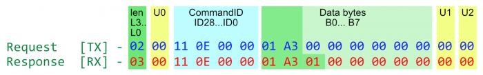
Structure of a block:
|0,0,0,0,L3…L0|U0|0,0,0,ID28…ID24|ID23…ID16|ID15…ID8|ID7…ID0|B0…B7|U1|U2|
| Data | Description |
|---|---|
| 0,0,0,L3…L0 | Information on length - value between 0x00…0x08 (byte(s)) |
| ID28…ID0 | Command ID according to command description |
| B0…B7 | Byte 0…7 \ Number of valid data bytes depend on the command and are encoded in the length parameter.\ On receive: Other bytes can carry values ≠ 0 (zero), and therefore should not be used for interpretation!\ On send: Value of unused bytes should be 0 (zero). |
| U0, U1, U2 | Unused blocks - Value should be 0 (zero) for sending data into the device.\ While receiving data from the device, those blocks also can carry values ≠ 0 (zero), and therefore should not be used for interpretation! |
The length of one block is always 16 byte.
On firmware versions 06.xx.xx and higher sockets are nonblocking. If data is not fetched fast enough from a socket it will be automatically closed.
Example
Buffer[0] = Length;
Buffer[1] = 0;
Buffer[2] = (ID>>24)&0xFF;
Buffer[3] = (ID>>16)&0xFF;
Buffer[4] = (ID>>8)&0xFF;
Buffer[5] = (ID>>0)&0xFF;
for (i=0; i<8; i++) Buffer[i+6]=Data[i];
Socket1->Socket->SendBuf((void*)Buffer, 16);
Functional Principle
All blocks received over an IP port are either routed to the central communication controller or to the internal CAN-bus, dependent on the Frame Type / Controller Type (see Introduction for further background).
All blocks of a defined type are routed to a connected IP port by either the central communication controller or by the CAN-bus, dependent on the Frame Type / Controller Type.
All data is in Motorola-format (MSB first)